Robotics Labs
Overview: The Robotics Electronics kit consists of many labs involving different ways to control the robot to do an expected outcome with the use of a switch and circuitry. The labs within this kit showcase the power of robotics, where a circuit can be used to program a robot to do a specific output. This is important when relating to the advancement in technology, because by creating robots, they are able to be commanded to complete tasks that humans cannot. These labs were completed over a course of many weeks in order to further my knowledge in electricity, understanding of components, and robotics.
Time Controlled Motion I
|
|
This circuit is wired so that the robot moves forward in steps, move-stop, move-stop. The 555 IC words as a time to produce pulses on the output. This turns the transistor on and off. When the transistor turns on, the LED and relay turns on too. When the relay is on, it applies voltage to the motors and makes them spin. This causes the robot to move forward. When the transistor is off, the relay does not get any voltage, making the robot not move, or pause. With the potentiometer in the circuit, the pulse speed can vary. When the potentiometer increases the resistance, the pulses slow down in speed, meaning that the robot moves for a longer period of time, but also stops for a longer period of time. When the potentiometer decreases the resistance, the pulses increase in speed, meaning that the robot moves for a shorter period of time, but also stops for a shorter period of time. On the left, the top video displays the robot's motion when the potentiometer is twisted so that it produces the maximum resistance. To bottom video displays the robot's motion when the potentiometer is twisted so that it produces the least resistance.
|


Time Controlled Sharp Right Turn
|
|
In this lab, the robot is programed to make timed sharp right turns. Similar to the previous experiment, the robot will move-stop, move-stop. This is done by using the exact same circuit, but switching the four wires of the motors. The wires are then reconnected in order to create a sharp right turn. Like the previous experiment, the potentiometer can be used to change the speed of the robot. By increasing the resistance, the robot will make larger turns, but stop for longer. By decreasing the resistance, the robot will make smaller turns, and stop for a shorter period of time.
|


Explorer I Robot
|
|
This experiment has the robot combine both a forwards and backwards motion. When the relay is not activated, (there is no pulse from the 555 timer IC) the robot moves forward. When the relay is activated, (the 555 timer IC produces a pulse) the robot moves backwards. The speed of the actions is dependent on the potentiometer setting. By increasing the resistance, the speed decreases, and by decreasing the resistance, the speed increases.
|


Explorer II Robot
|
|
This robot is controlled similar to the previous experiment; however, the motors are connected to combine two different motions, forward and backwards right turn. When the relay is not activated, the robot moves forward. When the relay is activated, the robot makes a backward right turn. The speed of the actions is dependent on the potentiometer setting. By increasing the resistance, the speed decreases, and by decreasing the resistance, the speed increases. When building this experiment, the wheels had no friction with the ground, so the robot would slip, rather than turn. To solve this, I rubber banded the wheels in order to gain some friction. Though not an ideal way to add rubber bands, there was not one that would extend the width of the wheel, so I had to compromise.
|


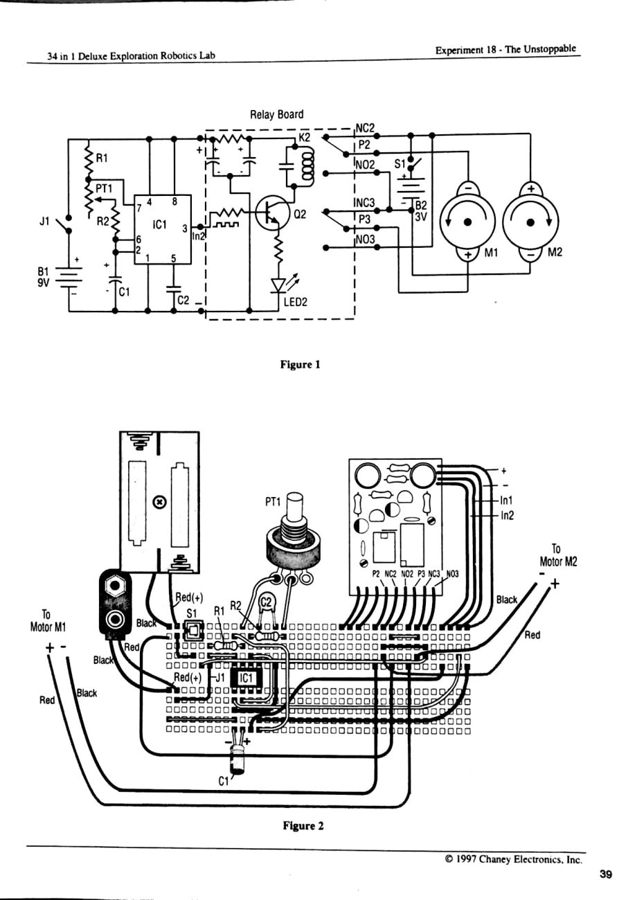
The Unstoppable
|
|
This robot is able to work its way in front of many situations. This uses the same timer circuit from the other experiments, but the motors are wired differently. This uses the two motors to create a backwards and sharp left turn motion. This combination helps the robot work its way from objects in the way. When the relay is unactivated, the robot moves backward. When the relay is activated, the robot makes a sharp left turn.
|

The Night Runner Robot
|
|
This robot is wired to operate in the backwards and hard-left turn motion, but only in the dark. The timer section of the circuit consists of a photocell which when receiving light, the resistance is low, causing the transistor to be off. When the light decreases, the resistance increase and a positive voltage is applied to the transistor, causing the circuit to conduct. This video was filmed close to the robot in order to cover the photocell. In the end, the robot stops because the photocell receives too much light.
|


The Day Runner Robot
|
|
The robot only operates when there is plenty of light. The timer circuit is the same one used in the previous circuit, but now the CDS cell in connected to the input "In1" on the relay board. Now when the CDS cell receives light, the resistance is low causing the transistor to conduct. When the light decreases, the resistance increases, causing the transistor to stop conducting. As shown in the video, when there is light, the robot moves; however, when the photocell is covered, the robot stops.
|


Infrared (IR) Vision
|
|
This is an electrical circuit that detects infrared light. The infrared transmitters used in remote control circuits can be used with this circuit. When the infrared receiver module (IRM) detects infrared light, it generates pulses to the base of the transistor. When the transistor conducts, the LED turns on, indicating the presence of infrared radiation.
|


The IR-Eye Robot
|
|
This robot only operates when infrared radiation strikes the infrared receiver module. Infrared radiation can come from various items, including television remotes. When infrared light strikes the IRM, the LED turns on and the relay is activated, causing the robot to move.
|


Obedient - IR Remote Controlled Robot
|
|
This robot is wired to move backwards when the IRM does not receive any infrared radiation, and to turn when infrared radiation strikes the receiver. The robot can be controlled to avoid obstacles and produce the motion wanted. The motors are wired to the relay to produce a backward motion when it is not activated, and to make a turn when it is. The relay is activated only when the circuit receives infrared radiation.
|


Robot Pet
|
|
This robot consists of an infrared transmitter circuit with a 555 IC which generates pulses to the LED. The IR LED emits IR light that when near an object, will bounce off and hit the infrared receiver module. When this occurs, the relay is activated and the motors produces a turning motion.
|


IR Obstacle Avoiding Robot I
|
|
This robot performs a forward motion until it either detects an obstacle or infrared radiation. The circuit contains an IR transmitter and has IR vision similar to what was built previously. This circuit produces infrared light from the infrared LED, which when an object is near, it the IR light bounces off and onto the infrared receiver module. This can also be controlled with a remote control in order to avoid objects before coming into contact with them. This is because the robot will turn whenever detecting infrared light, making it able to avoid obstacles.
|


Sound Detection (Robot Ears)
|
|
This circuit allows us to be able to turn on and off a relay on the relay board. The circuit uses an electret microphone to receive the sound and convert it into an electric signal. This signal is sent to the integrated circuit to be amplified. The 555 IC is installed so that it will produce only one pulse and will change the state of the output every pulse. This allows every sound to turn on and off the LED, which is connected to the output of the integrated circuit.
|


Big Ears Robot
|
|
This robot uses the sound detection circuit built in the previous experiment (Robot Ears). The motors are wired to the relay to produce movement every time a sound is detected by the microphone. A sound will put the robot in motion, and another sound will stop it. This robot is able to produce different motions, and can be changed by wiring the motors differently on the circuit board.
|


The Music Dancer Robot
|
|
This robot is created to move every time it hears music. When the sound stops, the robot does as well. In this circuit, the audio signal of the output of the integrated circuit is used to charge the capacitor to charge the transistor, which activates the relay to apply power to the motors. When the audio is cut, the transistors are no longer charged, inactivating the relay, causing the robot to stop until it hears a sound again.
|


Major Takeaways:
After completing these labs, I now have a deeper understanding of robotics and the electrical circuits behind them. Using infrared light, I can replicate how remote controls function in order to create the desired output. Even from afar, the infrared light travels to the receiver, meaning that even when standing a few feet away, the expected outcomes still occurred. With infrared light, the robots can be controlled from multiple distances to do a commanded action. Within these labs, I encountered a few problems. Most of the problems were simple mistakes in installing the components correctly. I would double and triple check to make sure everything is correct, in order to make sure not to damage any component. Also, I had multiple problems with the wheels. Initially, the wheels did not have any friction with the ground, and would slip, rather than move normally. To fix this, I added rubber bands; however, none were wide enough to extend the width of the wheel, so I had to improvise (there was a groove in the wheels and the rubber bands would fall in the groove, not touching the ground at all). Later, I added masking tape to get friction between the wheels and the floor, and that worked the best. The width was exactly the same as the wheels and provided the right amount of friction. Overall, this lab was a success and taught me the positives in robotics.
After completing these labs, I now have a deeper understanding of robotics and the electrical circuits behind them. Using infrared light, I can replicate how remote controls function in order to create the desired output. Even from afar, the infrared light travels to the receiver, meaning that even when standing a few feet away, the expected outcomes still occurred. With infrared light, the robots can be controlled from multiple distances to do a commanded action. Within these labs, I encountered a few problems. Most of the problems were simple mistakes in installing the components correctly. I would double and triple check to make sure everything is correct, in order to make sure not to damage any component. Also, I had multiple problems with the wheels. Initially, the wheels did not have any friction with the ground, and would slip, rather than move normally. To fix this, I added rubber bands; however, none were wide enough to extend the width of the wheel, so I had to improvise (there was a groove in the wheels and the rubber bands would fall in the groove, not touching the ground at all). Later, I added masking tape to get friction between the wheels and the floor, and that worked the best. The width was exactly the same as the wheels and provided the right amount of friction. Overall, this lab was a success and taught me the positives in robotics.
